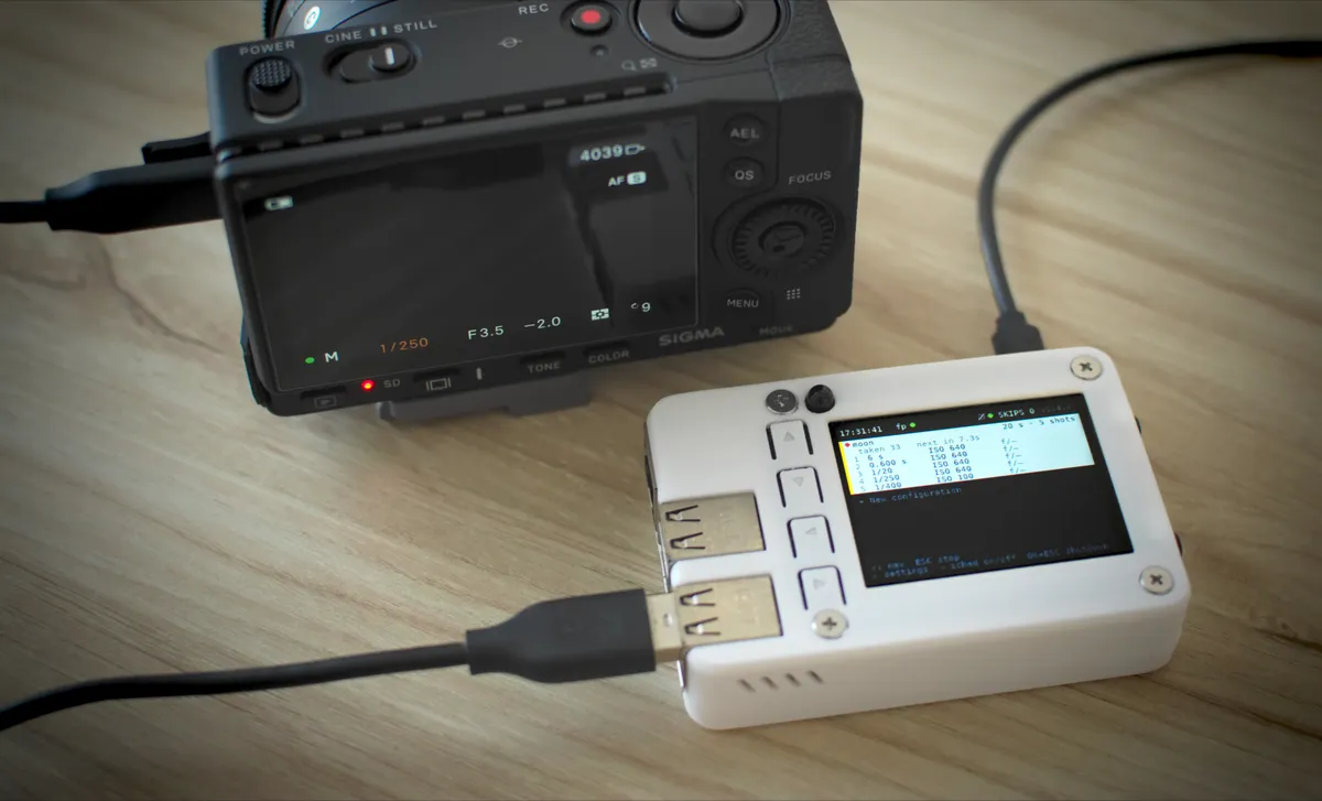
An intervalometer with the Raspberry Pi: getting ready for the 2026 eclipse
On 12 August 2026 there will be a total solar eclipse over the north of Spain, and that is the reason for this project. The plan is to capture it with a SkyWatcher MAK-127 telescope on a Go-to mount. For the camera we’ll use a Sigma fp, the full-frame body I have to hand. The MAK-127 has a focal length of 1500 mm, and on a smaller sensor the corona would be cropped.
The fp has its own intervalometer, but it falls short for this. During the eclipse you need bracketing to get more exposure latitude, and at least two very different settings: one for the partial phases and another for totality — that short minute and a half when the corona appears and the light drops several stops all at once. During totality we also want to shoot more often, to stretch that part of the video a bit, so the interval changes too.
One important thing is being able to jump from one setting to another in the middle of the timelapse without breaking the interval rhythm. If, right when totality starts, we switch from “partial” to “totality” —a different exposure and a shorter interval—, the next shot has to land when it should, without resetting the counter or throwing off the cadence, so there are no odd jumps in the Moon’s movement. On top of that, we want all of this to be as simple as pressing a button, or better still, automatic by date and time, because during the eclipse there will be no time to improvise.
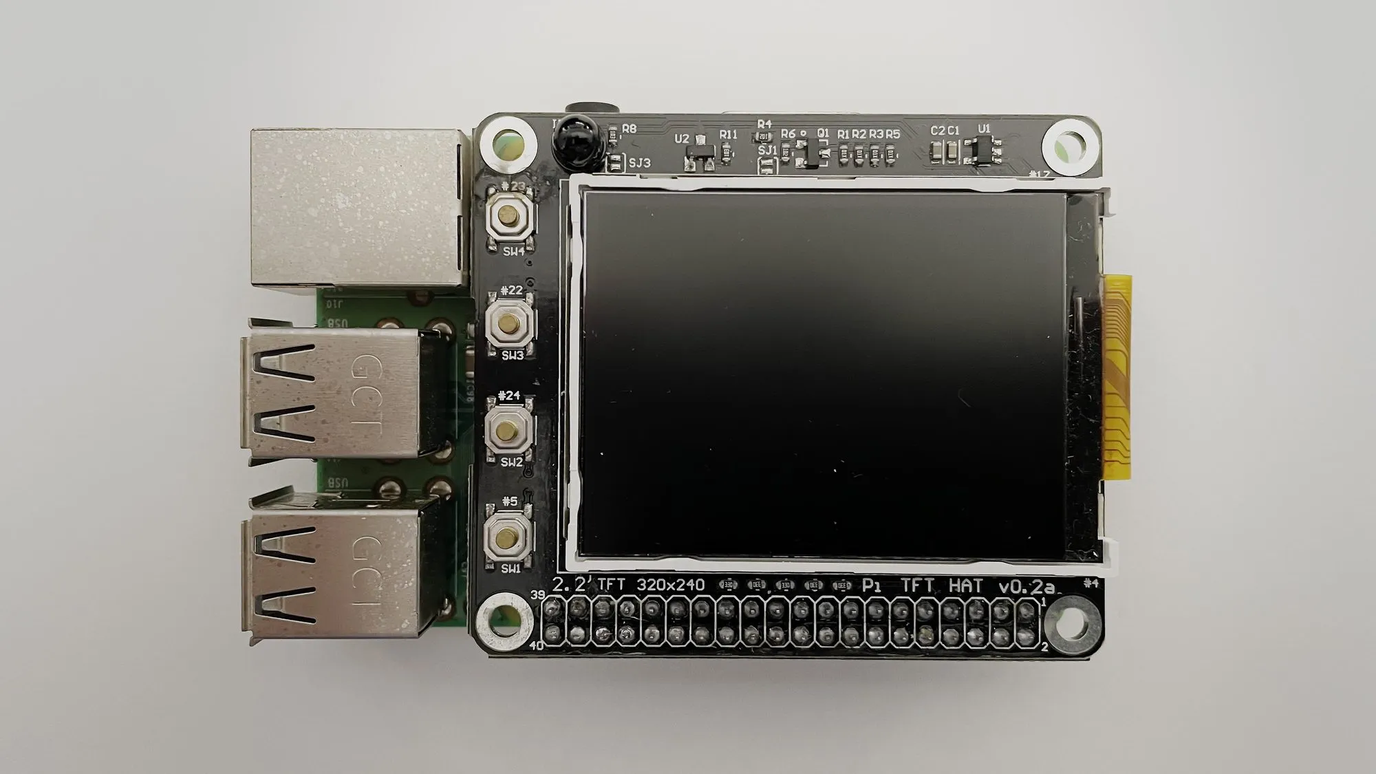
The device is a Raspberry Pi 3 with a 2.2” TFT HAT and six physical buttons. The fp is controlled over its USB port. It doesn’t have to be this exact model —it should work just as well on a newer Pi and screen—, I’m simply reusing hardware I already had in a drawer.
What follows is not so much about how the code is written as about the strategy for developing it with AI — Claude Code wrote 100% of the code.
Letting Claude deploy to the hardware
For development we work from a laptop and use the Raspberry Pi for validation
testing, deploying over SSH with rsync and restarting the service. The
first thing we did was make access easy — an SSH public key copied to the Pi
(you can do this from the Raspberry Pi Imager wizard when you write the card)
and an alias entry in ~/.ssh/config, so the agent gets in without a password
and without fighting credentials every time it needs the machine.
Every test on the real device —deploy, restart, look at the TFT, press a button— is slow, especially if you have to do it by hand. So the strategy was to keep hardware testing to a minimum, making almost all the development and testing happen on the laptop itself, and, when it is time to go down to the real hardware, giving the agent tools to inspect it without needing to step in manually.
And that is the idea behind the whole project: reduce manual work to a minimum, setting up the environment so the agent can write, test and fix on its own, and only step in when it is really needed.
Getting the screen and buttons to respond
First of all, check that the TFT draws and that the buttons are read. The Pi boots straight into the app, full screen, with no login or console behind it. That is three pieces: a systemd service that launches the app on power-up, the system console pushed off the panel, and no auto-login.
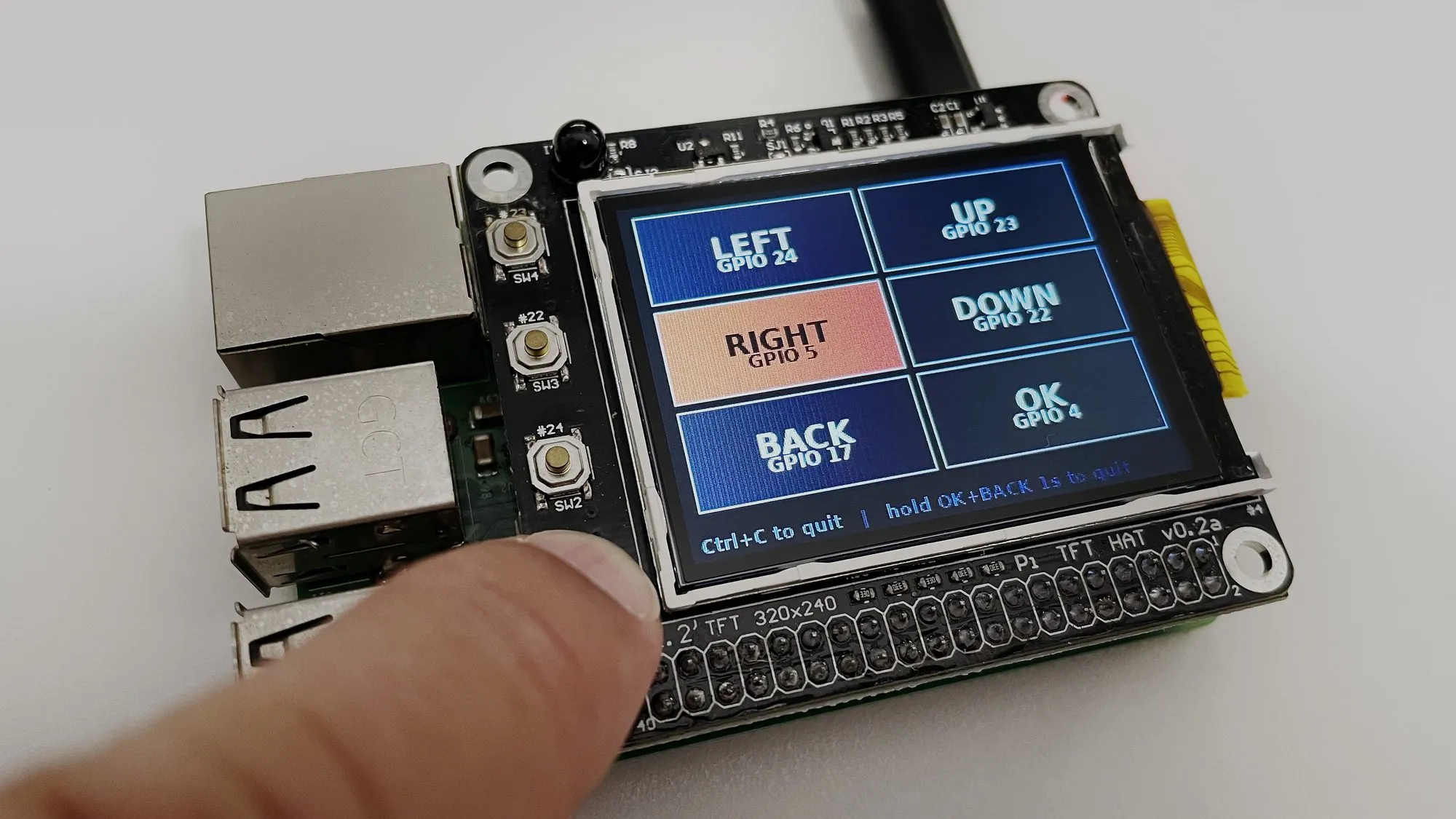
To check it, we asked Claude Code for a test screen — a simple interface with the six buttons, each with its GPIO pin, lighting up when pressed — and we tried it with a finger.
Making sure we can talk to the Sigma fp
This one is basic. If we can’t talk to the camera there is nothing to do, so before thinking about the intervalometer logic there’s a feasibility test to confirm the communication works.
Again, we asked Claude for a basic test and it went for
sigma-ptpy, a PTP (Picture
Transfer Protocol) library in pure Python, ruling out Sigma’s official SDK
—x86_64 binaries, not viable on a 32-bit ARM—.
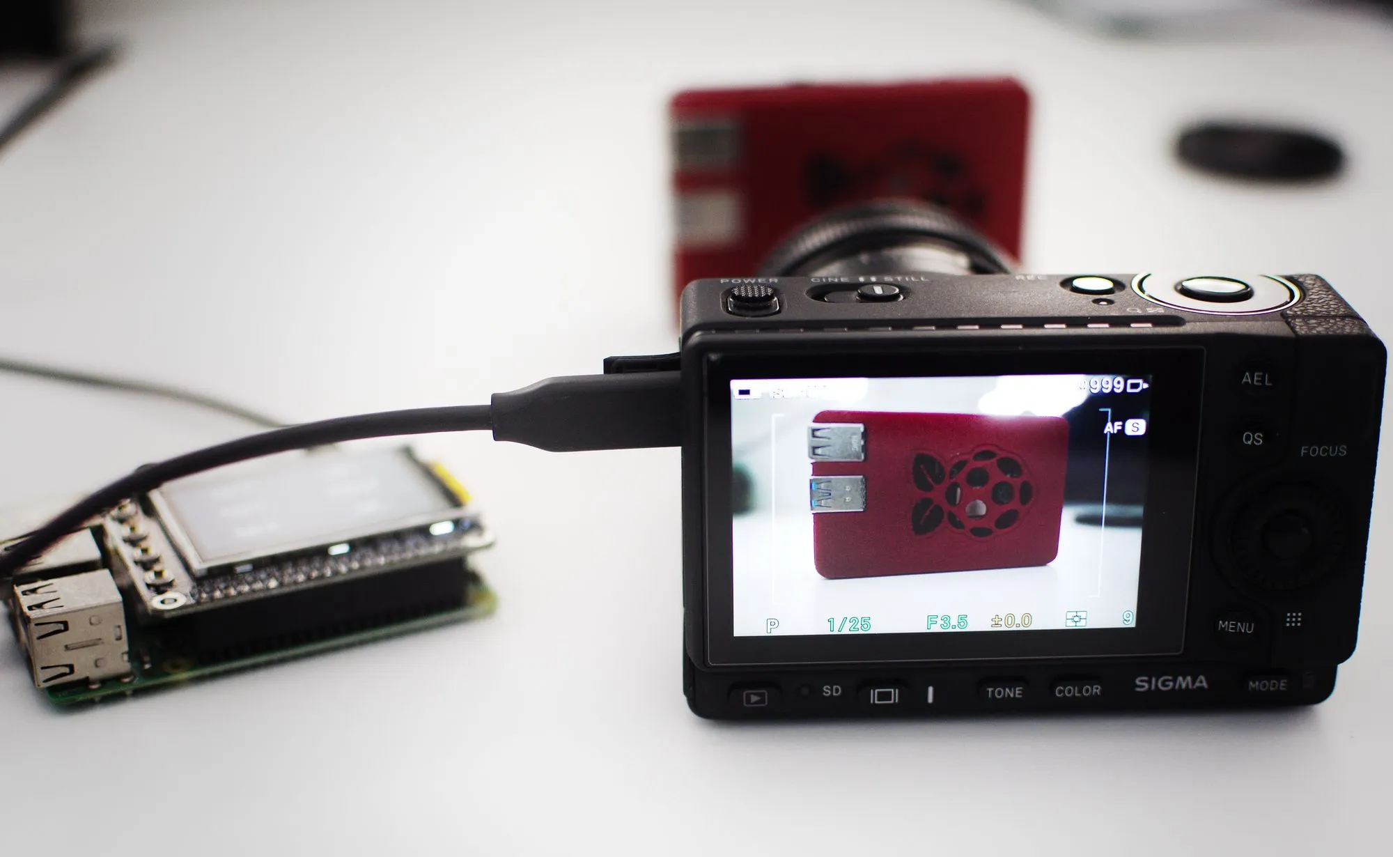
Claude Code implemented this part almost on its own, iterating straight against the Pi over SSH. We put the camera, connected to the Pi, into “camera control” mode, and we could watch it take photos now and then and check the results. We only had to point out a couple of things that didn’t work the first time —to do with auto mode and manual focus—, but little else.
Abstracting the hardware
Once we knew the hardware —screen, buttons and camera control— worked, we asked Claude to create an abstraction layer that could take several implementations. For the buttons, for example, one implementation reads the GPIO directly and another receives simulated presses. For the display, one version writes straight to the screen and another generates images. And for the camera, one talks to the real camera and another fakes it. That way the software can run both on the Raspberry Pi and directly on the Mac, with no LCD, no buttons and no real camera communication.
This step was key to speeding up the work. We gave the agent full autonomy to develop all the logic, and we could test at several levels:
- On the laptop, without writing to the Raspberry Pi and without needing to see the interface — for example, to test the firing logic.
- On the laptop, simulating the interface to check it looks as expected (by inspecting the PNGs it generates).
- Straight on the hardware, where the agent deployed the code to the Pi and, through a small local HTTP server, simulated button presses and captured the screen (it was funny to watch the screen change on its own without touching anything).
The abstraction and the mock versions made it possible to cover the whole logic with a battery of more than 250 tests that runs in a fraction of a second on the Mac. Every bug that showed up was closed with a test that reproduced it, so the agent could rewrite and reorganize without fear of breaking what already worked, and regressions were caught on the laptop long before going down to the hardware. The user interface came out almost right the first time, because the agent could read the PNGs with no help and check that everything rendered correctly.
Validation testing
The first time the full system went down to the Pi, it was losing shots — it marked them as skips. Without looking at the code, just watching how the interface refreshed, you could tell the implementation wasn’t very efficient and that photos were being lost to small refresh delays. In the loop, for instance, it checks that it isn’t time to shoot yet, repaints the whole screen, and by the time it checks again the moment to shoot has already passed.
We asked the agent to verify what we were telling it, again without going into the code, and we suggested a couple of ideas, like handling the events asynchronously and refreshing the image only when something changed instead of repainting on every pass. It rewrote the loop along those lines and, on the next test on the Pi, the skips were gone.
The enclosure
Once the software was done, it was time to put it all in a box to make it manageable. We started from an enclosure already designed for the Raspberry Pi 3 —the Malolos from Printables— and adapted it to fit the 2.2” screen and the six buttons. we did the adaptation in OpenSCAD, also with AI, but that’s material for another article.
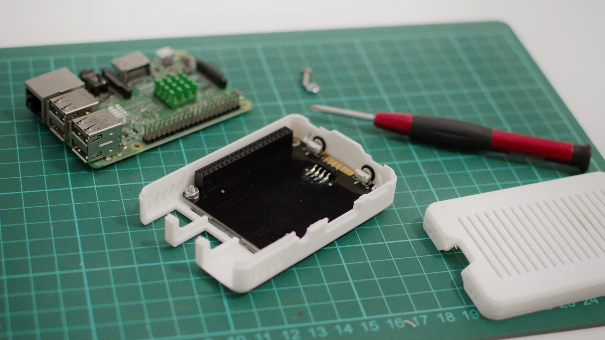
The result came out fairly compact, boots on its own when you give it power, and is driven with the six buttons.
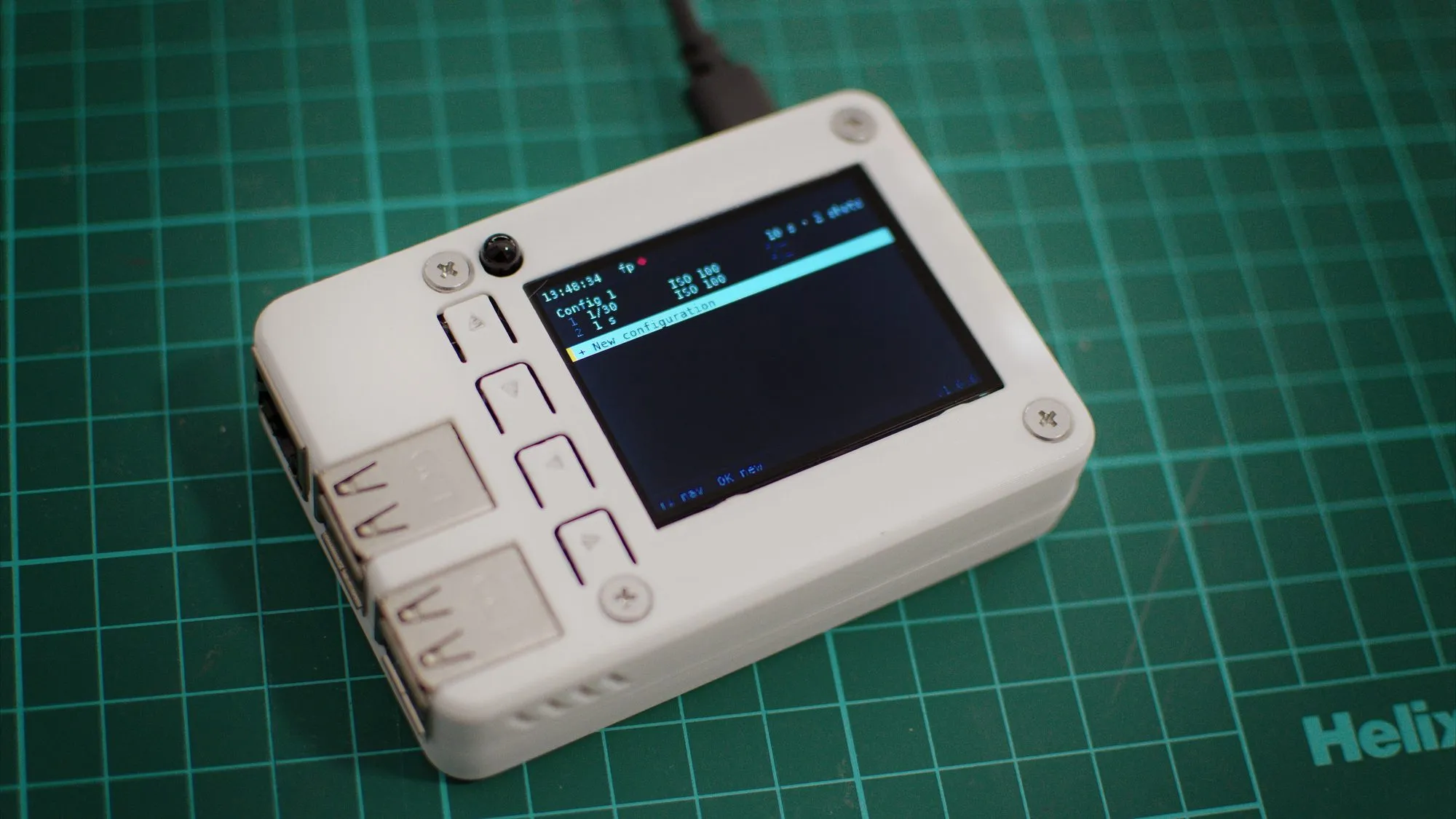
The software is released under the MIT license and available on GitHub. A configuration can be manual —one to nine shots, each with its shutter time and ISO, for bracketing— or automatic, letting the camera meter each frame. It boots on its own, reconnects to the camera if the USB drops, and stores everything in a simple file you can also edit over SSH.
The real test
To test the intervalometer we made a timelapse of the Moon rising over the horizon after sunset. The Moon is very bright, and to keep it from blowing out you have to bring the exposure down, which darkens the rest of the scene. To avoid that trade-off we used heavy bracketing —5 shots 3.5 stops apart—, merged with HDRMerge and graded in DaVinci Resolve to keep the detail in both the Moon and the rest of the scene without visible noise.
Here is the result:
The rehearsal went well. The real test will be on 12 August.
Update. The intervalometer has kept growing since that first version. Today it’s no longer just for the Sigma fp: it also works with the Nikon D5600 —that hardware abstraction layer was exactly what made it possible to add a second camera without touching the logic— and along the way it has gained scheduled start by date and time, WiFi setup from the device itself, and other improvements for creating configurations.
References
- The
fp-lapseproject code on GitHub - HDRMerge
- The original Malolos enclosure and the adaptation with a 2.2” TFT and 6 buttons.
- Geekworm’s 2.2” LCD HAT wiki.