
Vibe coding for 3D design with OpenSCAD and Claude Code
OpenSCAD is a tool for designing 3D models from code. It has been around for a while —the latest stable release is old by now, though development builds keep coming— and its design paradigm has little to do with visual modeling applications like FreeCAD, SolidWorks or Fusion 360.
I first came across OpenSCAD many years ago, when I got my first 3D printer, an Arduino Materia 101 (essentially a Sharebot Kiwi 3D) that I bought as a kit and assembled myself. I needed something to create the models with, and OpenSCAD was the easy option for me, since I was already comfortable with code-driven CSG thanks to the POV-Ray raytracer, which I found through an article in PCManía, a Spanish computer magazine from Hobby Press — those were the days.
OpenSCAD designs are, in essence, code in its own language. Objects are modeled with operations on basic primitives —cubes, cylinders, spheres— or by extruding a polygon.
AI is good at generating code, and OpenSCAD is no exception. But generating code is one thing and doing vibe coding to design parts is another. Over the course of the article we’ll look at the repository structure I built as a harness around Claude Code to design printable parts.
Project structure
Everything lives in a monorepo, organized so that whatever is already solved gets reused. The unit is the project, each one with its folder under projects/. Projects do not depend on each other — they are only allowed to depend on components and libraries:
- Components (
components/) — modules reused across projects. They are specific physical parts, and each one has an associated project where all its documentation lives. - Libraries (
lib/) — generic reusable modules, with no associated project. They hold the very basic primitives everything else builds on.
Dependencies only go downward —projects → components → lib, and a project can pull from lib directly— and nothing ever depends on a project.
There is also a tool that serves the catalog in the browser, to take in everything you have designed at a glance. One card per project with its 3D render and, inside it, each printable part, its drawings and its documentation.
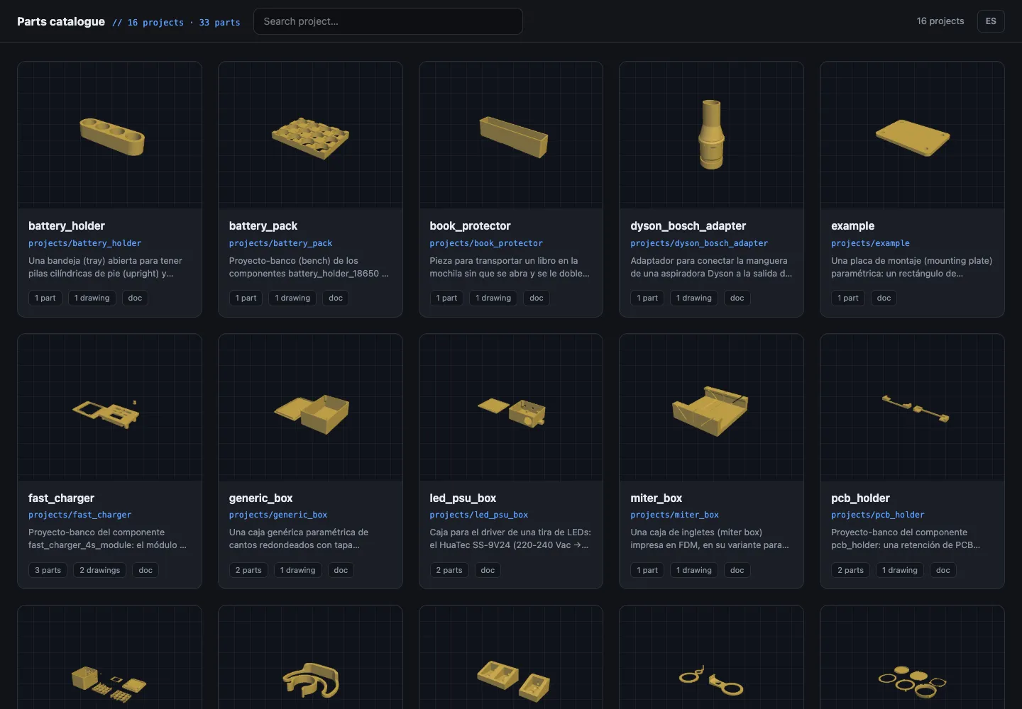
The catalog served locally with ./catalog.sh. It shows every part in one pass, instead of opening them one at a time.
The harness
Beyond the projects themselves, the repo carries a set of pieces that shape how the agent —Claude Code— behaves when designing 3D parts. Harness here means an environment around the agent, not a library it imports.
Layered context. A root CLAUDE.md defines the repo’s architecture and conventions, and each layer (projects/, components/, lib/) and each project carries its own with its specific rules. Every fact is defined in exactly one place and everything else links to it — the root keeps a map of who owns what, so the agent finds the rule without loading everything.
Reference documentation. docs/ holds the rest — a glossary that pins down the CAD and 3D printing vocabulary, the construction rules and the tooling guide. It also fixes code generation conventions, such as the MEASURED annotation (verified against the physical part) or ADJUST (an estimate).
Skills — the workflows. Two skills drive the design depending on where you start. Starting from a design spec, the agent asks to clarify the intent and the specific dimensions, leaning on cheap test pieces that get printed to verify each fit against the real part. Starting from an existing STL instead, the agent analyzes the design first to identify its features.
Subagents. Two agents with fresh context —to keep them unbiased— back those workflows. stl-analyzer looks at the part —renders and cross-sections— and returns a map of its features (bores, counterbores, chamfers, walls) before any modeling starts. design-conventions-reviewer acts as an auditor, checking whether the design follows the established rules and conventions.
Hooks. Two hooks close the system. A guard blocks raw trimesh and hand-rolled OpenSCAD calls — everything goes through the repo’s tools. And a nudge picks up on the prompt that it is a design job, and reminds the agent to invoke the skill that applies instead of improvising the procedure.
Tools. The utilities —written in Python— (uv run tools/...) are what give the agent eyes: validating that the part is printable and that the pieces don’t collide (check.py), sectioning it along planes and browsing those sections in a GUI (slice.py, slice_viewer.py), viewing it whole in 3D with a deviation heatmap against a reference (render3d.py), reconstructing the features of a mesh (analyze.py) and diffing two designs, scoring outline, holes and volume separately (compare.py). Then the preparation utilities —relocating vendor meshes, smoothing faceted DXF contours, dimension drawings with provenance by color— and a health_check.py that verifies the whole environment before you start.
Benchmarking: the same task with and without the harness
The truth is that Claude Code can generate OpenSCAD designs without any of this tooling. In fact, its natural tendency is to build its own STL analysis tools on the fly, even when it already has a set ready and waiting.
As a rule it is better to have a small set of generic tools than many specific ones, as explained in this Vercel article. Even so, during the first designs I watched the agent write the same kind of Python with trimesh over and over to inspect meshes —sometimes more successfully than others— so I chose to pin down that set of utilities with the lessons learned from those first designs.
Still, after several iterations it was time to test how much the harness actually buys — pose a problem and let the agent solve it with and without it.
The test was to generate a 3D model in OpenSCAD from designs that already existed as STL. Only two iterations. The first presenting the STL with the instruction to reproduce it, and a second one after the feedback I gave once I had inspected what came back.
To make it fully autonomous within each iteration, I created three agents using independent Claude Code sessions. One designed the parts with all the tools, another without them, and a third acted as orchestrator through a local HTTP broker, sending the same tasks to each agent and waiting for them all to finish. The whole thing ran on its own for more than two hours for the four parts.
I used four real parts published by the community on Printables (credits at the end). These are the results for each one:
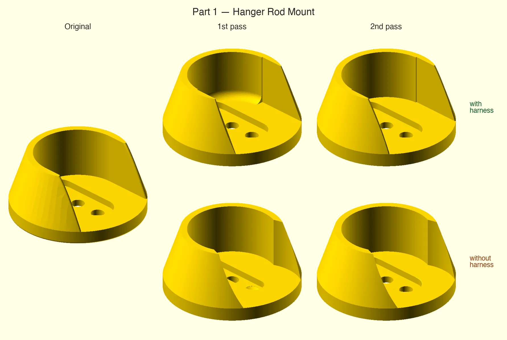
Part 1 (Hanger rod mount). On the first pass the harness almost nails it, while the control leaves odd narrowings in the recess. On the second the harness closes it out. The control improves the holes and the pocket, but the narrowing is still there.
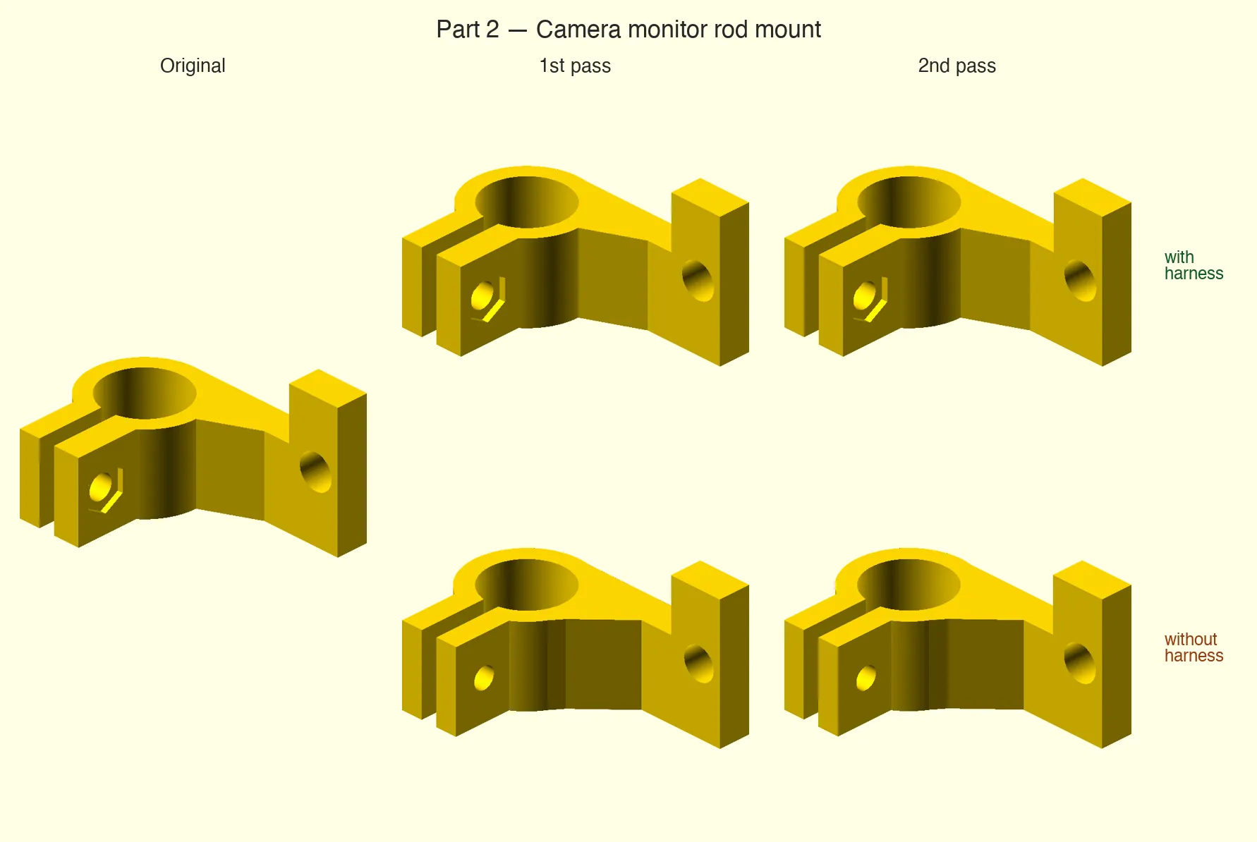
Part 2 (Camera monitor rod mount). The harness got it right on the first pass. The control, on both, still misses the nut pocket and leaves the holes off-center.
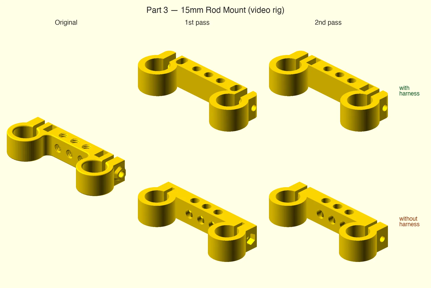
Part 3 (15mm rod mount). Both passes improve the shape, but neither ends up usable — hex nut pockets misplaced or blind, and holes still capped on one side.
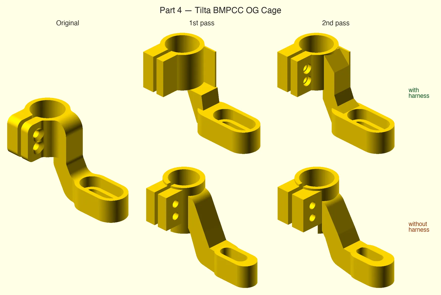
Part 4 (Tilta BMPCC OG rod mount). Even though the version without the harness ends up looking closer, its screw slot is wrong — no seat for the screw head, and off-center. The harness version does get it right.
At a glance almost all of them look like the original — but once you get into the details there is a clear improvement in the harness version, which respects tolerances, dimensions and slots far better.
In practice
Since those first tests I have kept using it for new designs — enclosures for electronics modules, adapters, accessories.
Vibe coding to design parts has worked out really well. Getting from an idea to something printable has never taken me so little time.
In some cases the input was a simple prompt describing what I wanted, plus a photo of the PCB on a grid with a few dimensions when what I was after was an enclosure for it. In others, I expressed the idea by pointing at other projects already in the repo.
It is not only that it gets it right with practically a single prompt, but that every so often it surprises me with an interesting design. And the more designs pile up, the better the system works, because it has more examples of how to solve certain parts — grip shapes (snap-fit or screws), pockets, fits. Often it is enough to say “use the same kind of grip as project such-and-such.”
Another thing I have found especially useful is Claude Code’s remote control mode from the phone — the agent keeps showing me images of what it is building and I can correct it, even by voice.
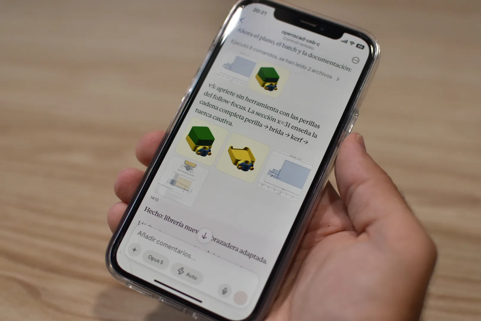
Designing without sitting at the computer. The agent sends the renders and the cross-sections, and you interact with it by typing or by voice.
I have published the skeleton of the repository on GitHub, with the full harness, its documentation and one example project — as a starting point for anyone who wants to adapt it to their own work. Any feedback is welcome — feel free to .
References
- Project: openscad-monorepo — the skeleton of the harness
- Part 1 — Hanger Rod Mount, by Tumblefluff
- Part 2 — Camera monitor rod mount, by ReMatrix
- Part 3 — 15mm Rod Mount for Video Rig – Universal Support Bracket, by dalbyte
- Part 4 — Tilta BMPCC OG Cage 15mm Rod Mount, by Ash