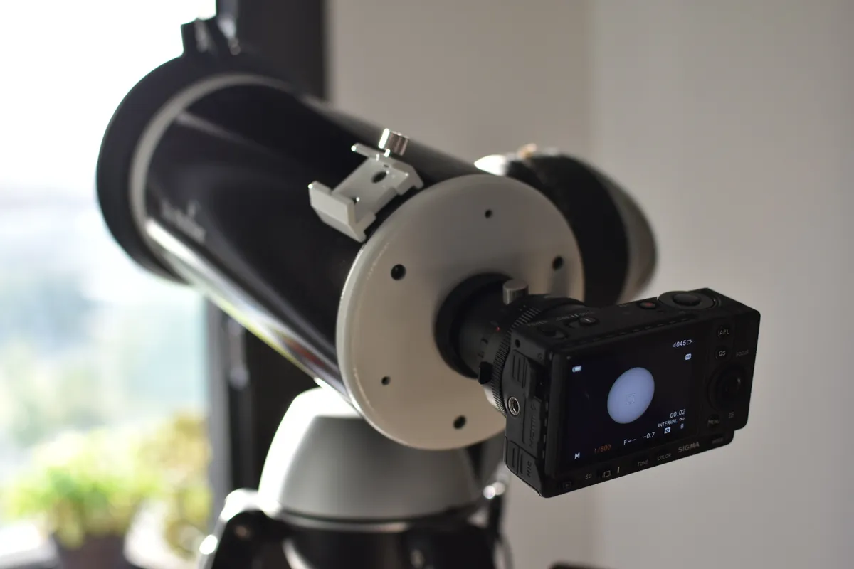
A magnetic solar filter for the Mak 127
A telescope pointed at the Sun is a funnel for light. The Sky-Watcher Mak 127 gathers far more light through its 127 mm aperture than a pupil lets in, and concentrates it into a few millimetres, so with nothing in front of it the camera sensor lasts seconds. If there is an eye at the eyepiece instead of a camera, the damage is worse and it gives no warning.
A full-aperture solar filter — one that caps the front of the tube — is mandatory to look at or photograph the Sun. During a total eclipse, though — like the one coming on 12 August — there is a brief window where the Moon covers the Sun completely.
The main requirement follows from that — it has to come off and go back on quickly, without moving the telescope much. During totality the filter has to be off for the corona to show, and back on before the first sliver of the photosphere returns. From where I’m planning to watch, totality lasts about ninety seconds, so there’s no room to improvise. On top of that, any force on the tube introduces vibration and shifts the framing, so the whole thing has to happen with barely a touch.
Everything else falls out of that:
- Baader AstroSolar Safety Film OD 5.0, the grade rated for both photography and visual use. Cheap, and it performs well.
- A magnetic quick release, the same approach plenty of commercial lens filters use.
- A friction fit onto the telescope, with self-adhesive foam tape cut to length — the same trick I’d already used for custom lens caps.
- Printed in PETG, which copes better with the temperatures involved.
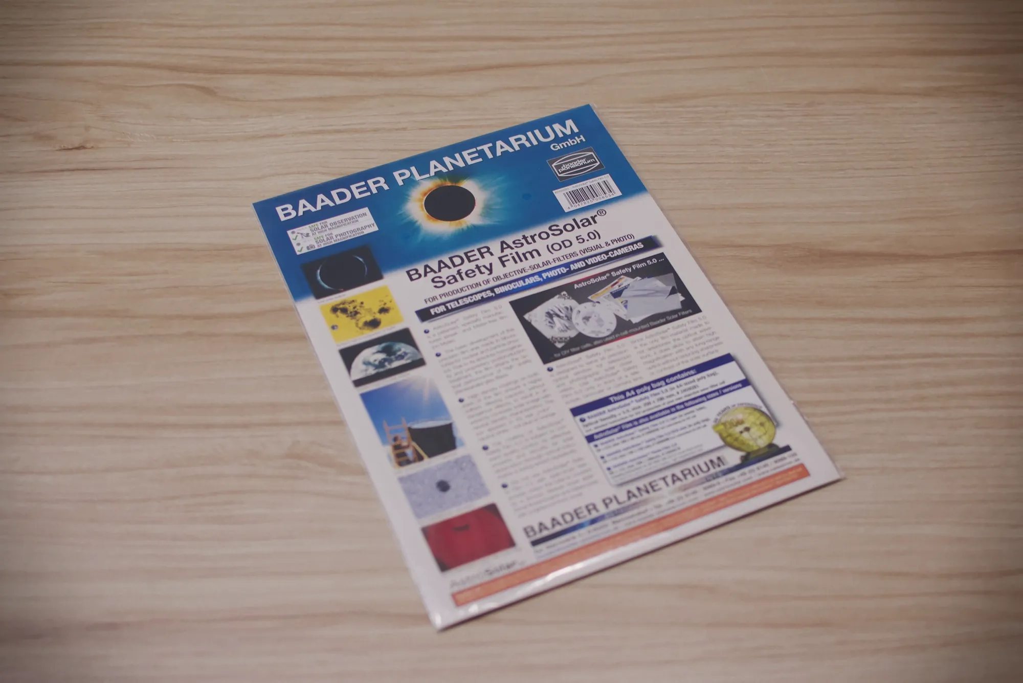
The film as it comes. One sheet is enough for several filters.
Designing the structure
For the modelling we leaned on the agentic OpenSCAD setup we’ve written about before. Since I already had a fairly clear idea of what I wanted, rather than asking the AI for the whole thing in one go we went piece by piece.
First the base. We measured the diameter of the telescope and designed a small test piece to print and check that the fit against the foam tape was right, before burning hours of printer time on the full ring.
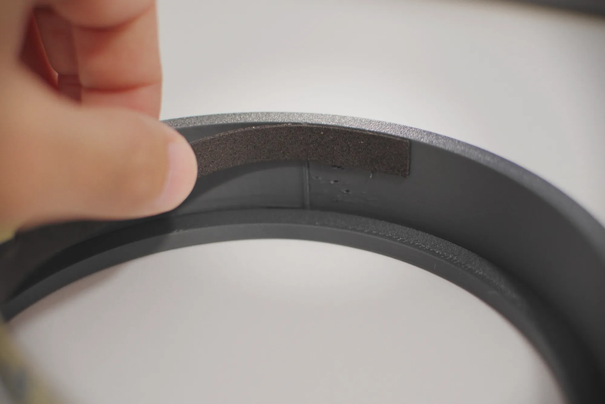
The foam tape on the inside of the ring, so it grips by friction.
With the measurement confirmed, we could design the base itself. The constraints were clear: it had to seat on the Mak 127’s tube, leave an outer shoulder with enough room for the magnets, and still fit the 180 × 180 mm bed of the Prusa Mini, which is the 3D printer I have.
We added a lip so the next piece — the filter cell — sits flush once the magnets pull it in, and a relief so it can carry a tab to pull on. That lip meant the ring had to print standing on its rear face, growing forwards with the lip ending up on top. To keep the underside of the lip from becoming an overhang, we tapered the diameter gradually, so it prints with no support material.
We decided to bury the magnets — neodymium, 6 mm diameter by 4 mm thick, eight per part — adding a pause partway through the print. That way they end up hidden and cannot fall out. It is worth watching the polarity as they go in, so the parts attract each other instead of pushing apart.
That was the plan. During the print, some of the magnets jumped out and stuck to the nozzle. Luckily I managed to pause quickly and glue them down with superglue before resuming.
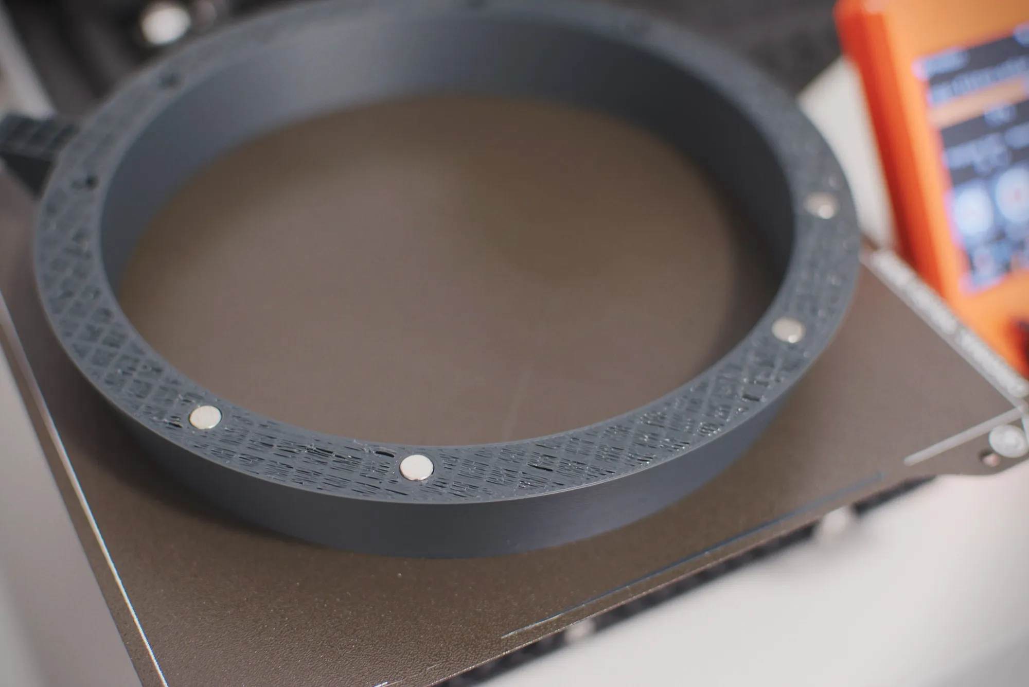
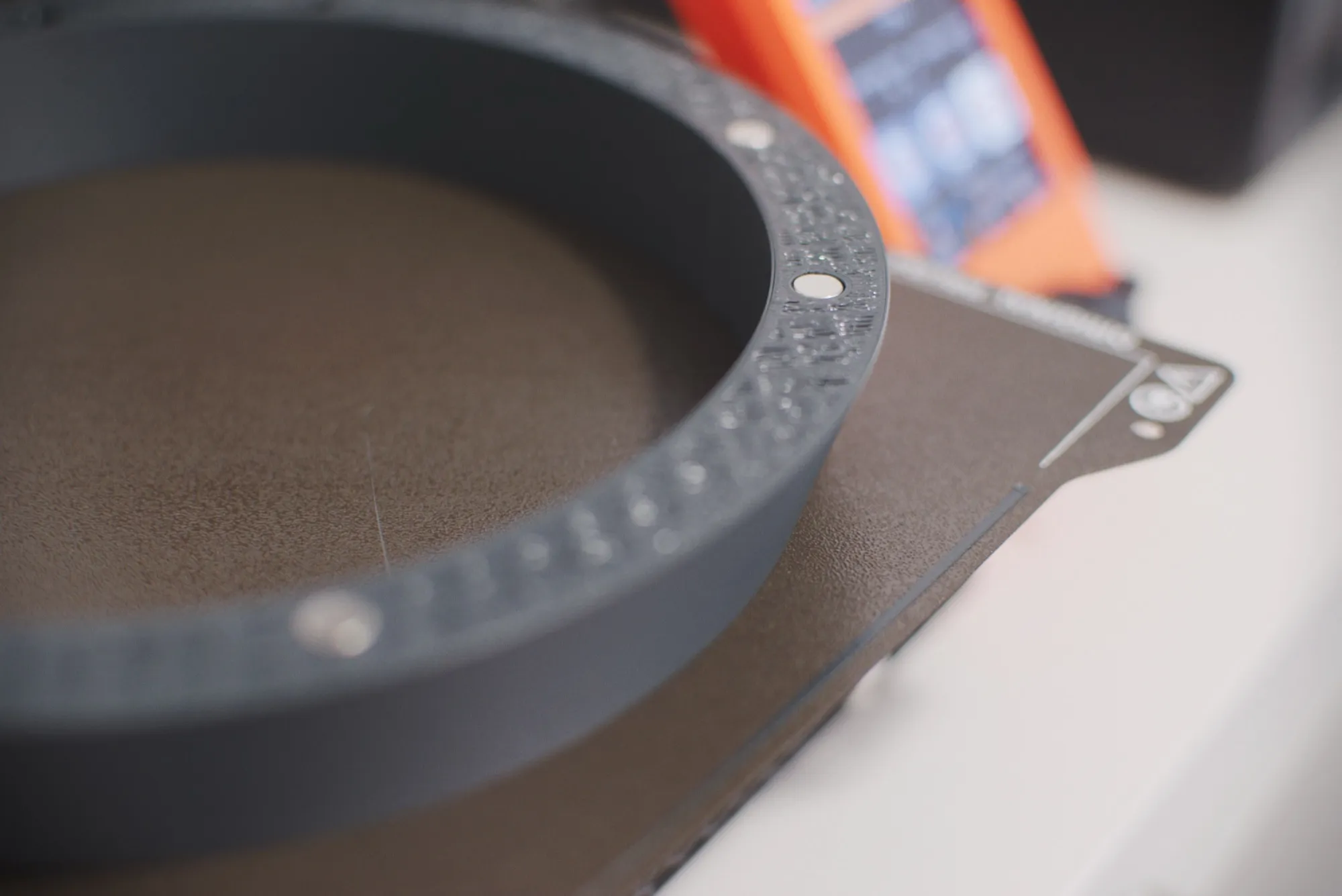
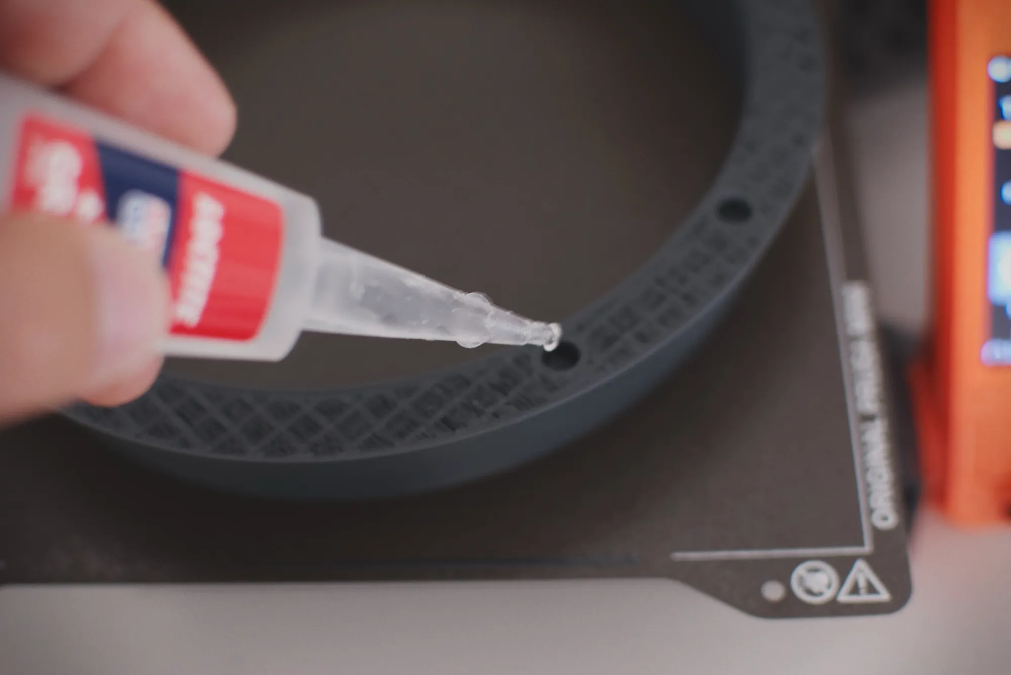
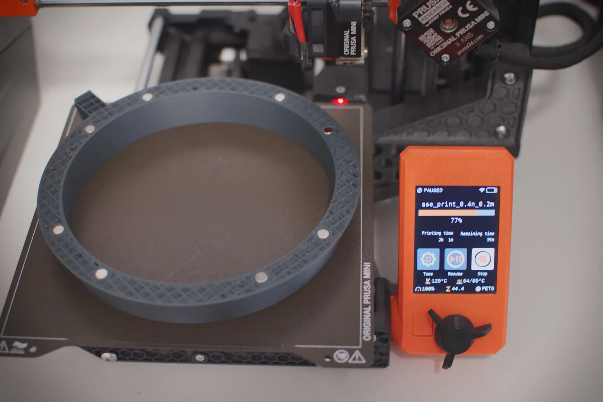
The pause, the magnets seated and glued down before the print resumed.
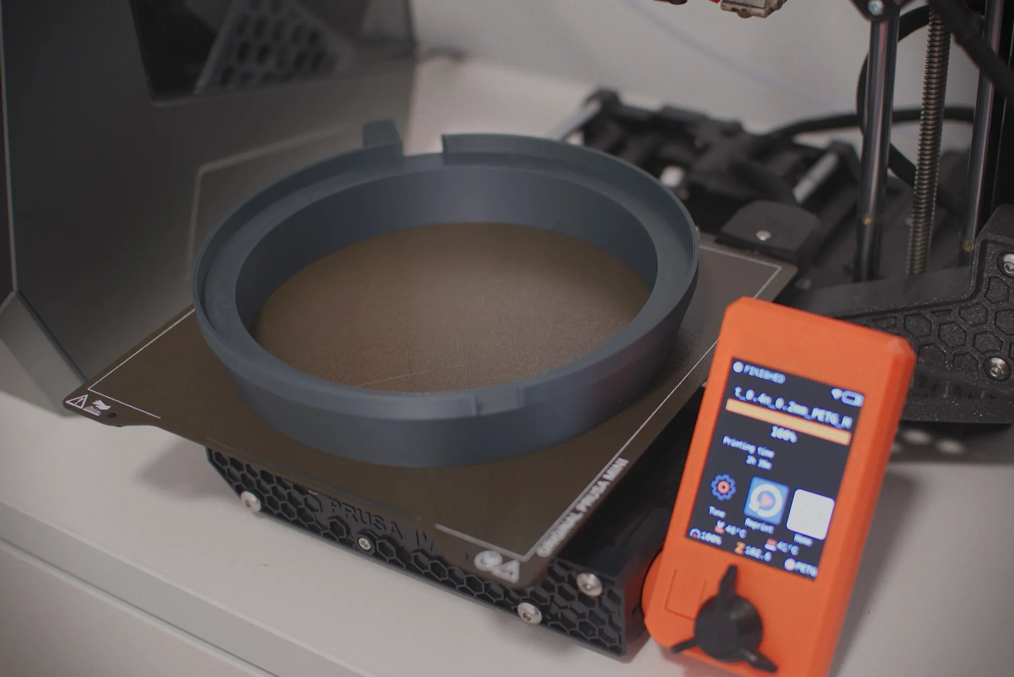
The base finished, magnets sealed inside.
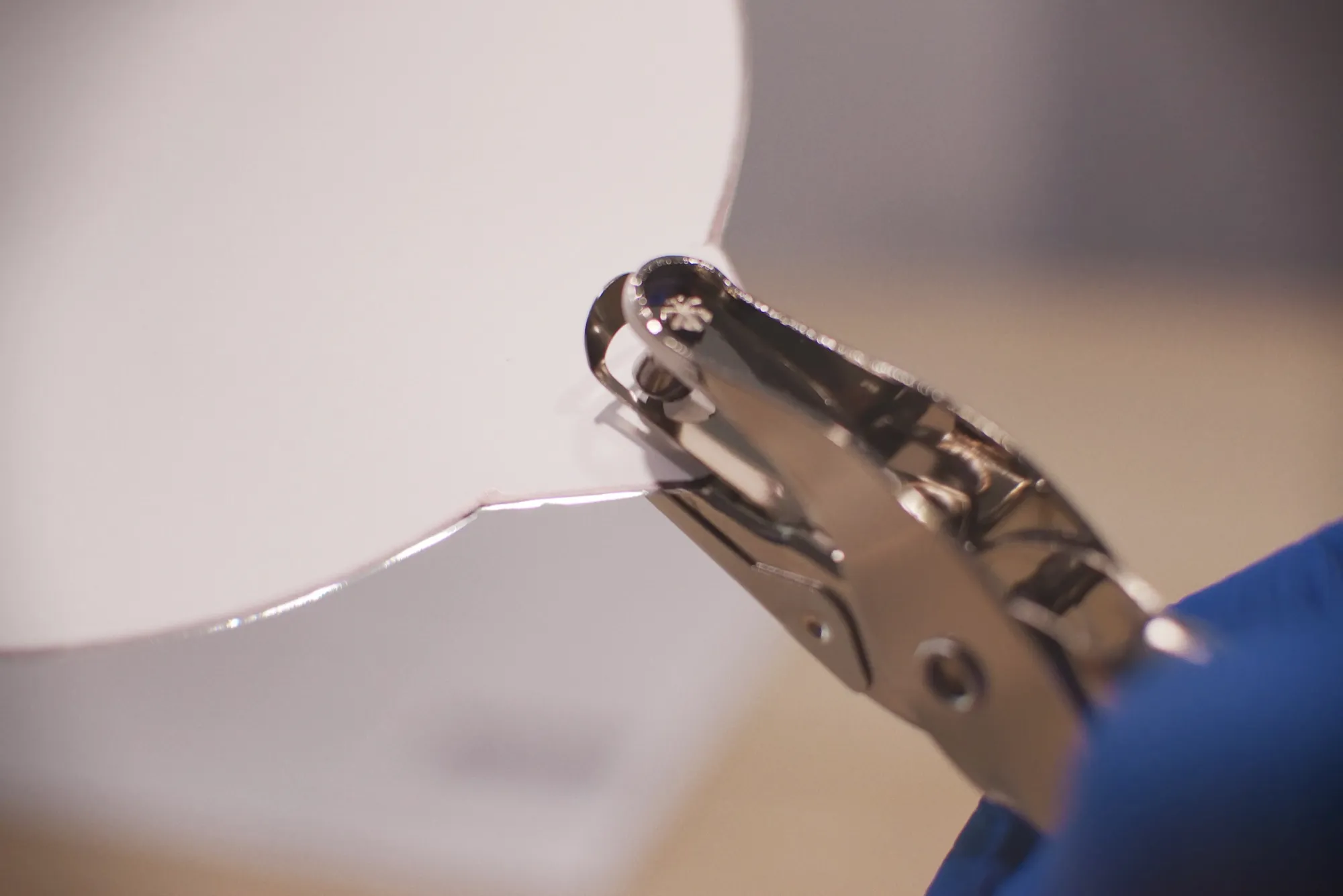
Next comes the filter cell. The key point here is that the film must not be stretched drum-tight, because it expands and contracts with temperature. The solution for a solid grip without stretching it was to punch holes in the film with a standard 6 mm paper punch and run a screw through them to hold it at those points.
That turned the cell into two halves bolted together with four M3 screws and their heat-set inserts. As well as making assembly and film replacement easier, it lets the screws double as the pins through the punched holes.
Both the base and the cell carry a tab, which is what lets you grab the filter to pull it off. We shaped them so that pinching between thumb and forefinger levers the two parts apart — the thumb rests on the base’s tab while the forefinger pulls on the cell’s — so the force stays between your fingers and never reaches the telescope. We also added a notch on the underside to make it easier to line up when putting it back.
With the tab, the part was a tight squeeze on the 180 × 180 mm bed, so we rotated the print 45° to make the most of the diagonal.
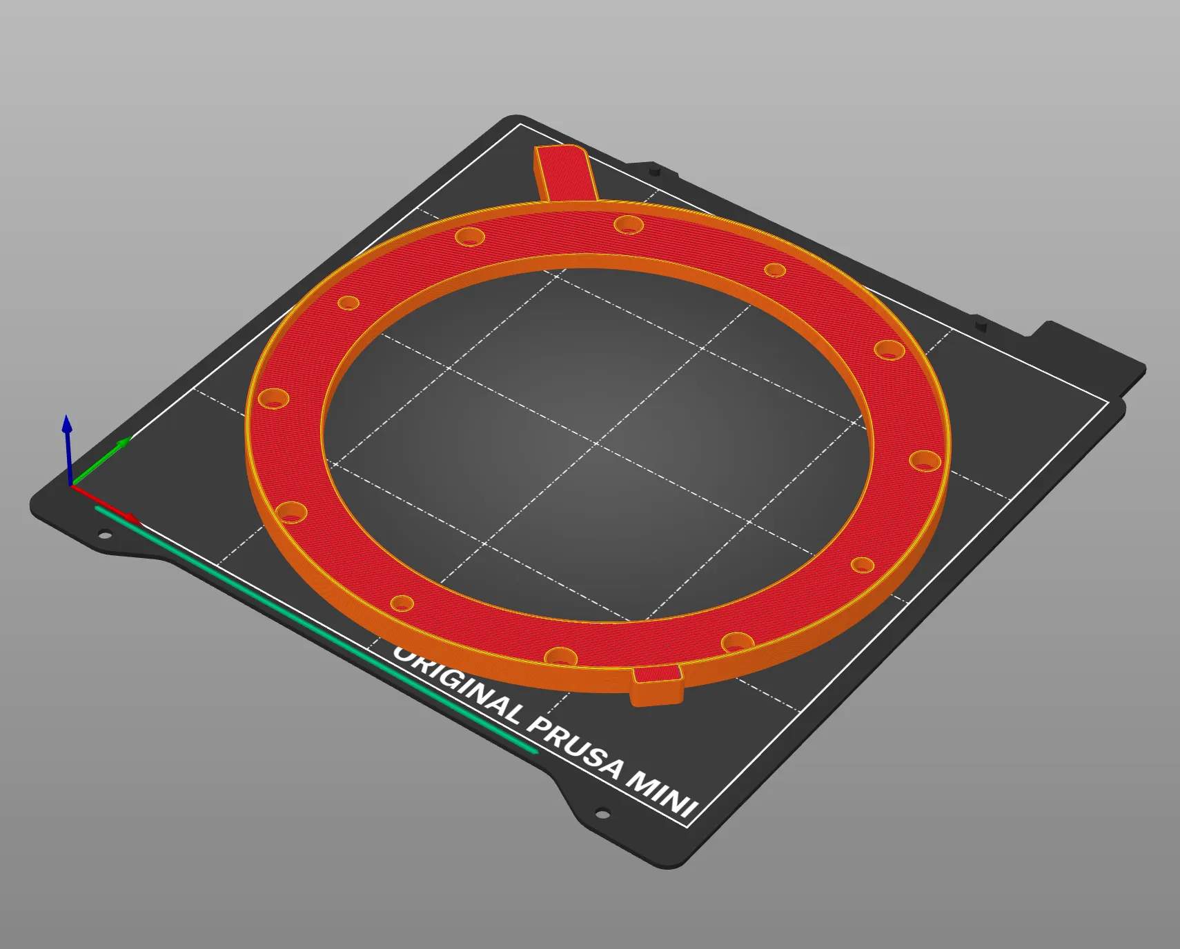
Turned 45° it fits across the diagonal of the Prusa Mini’s 180 × 180 mm bed.
Assembling the structure
With the parts printed, on to assembly. The heat-set inserts go in with the tip of a soldering iron, and they take the M3 screws that close the cell.
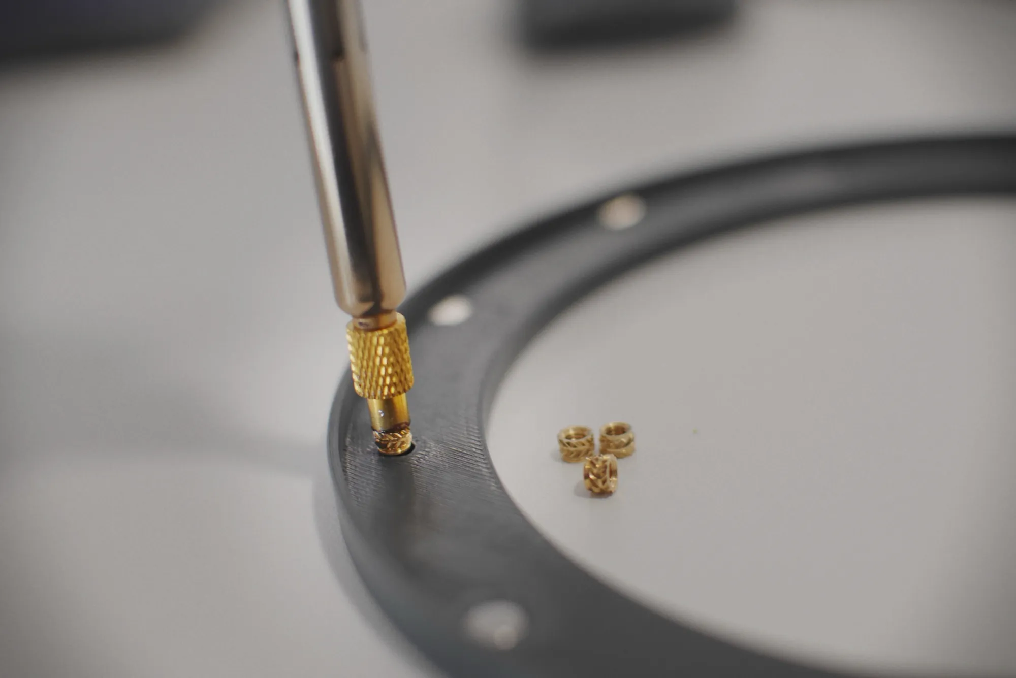
The heat-set inserts, driven in with the soldering iron. The M3 screws will double as the pins through the punched film.
Cutting and mounting the film
Since the whole design already existed, a cutting template cost nothing — it makes it easy to trace the outline onto the Baader sheet, punch holes included.
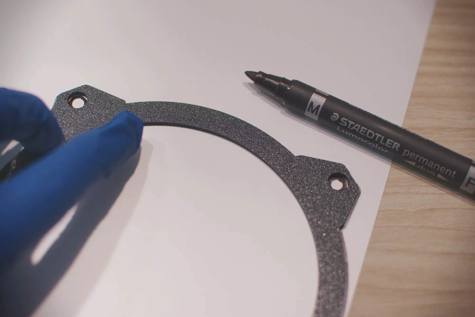
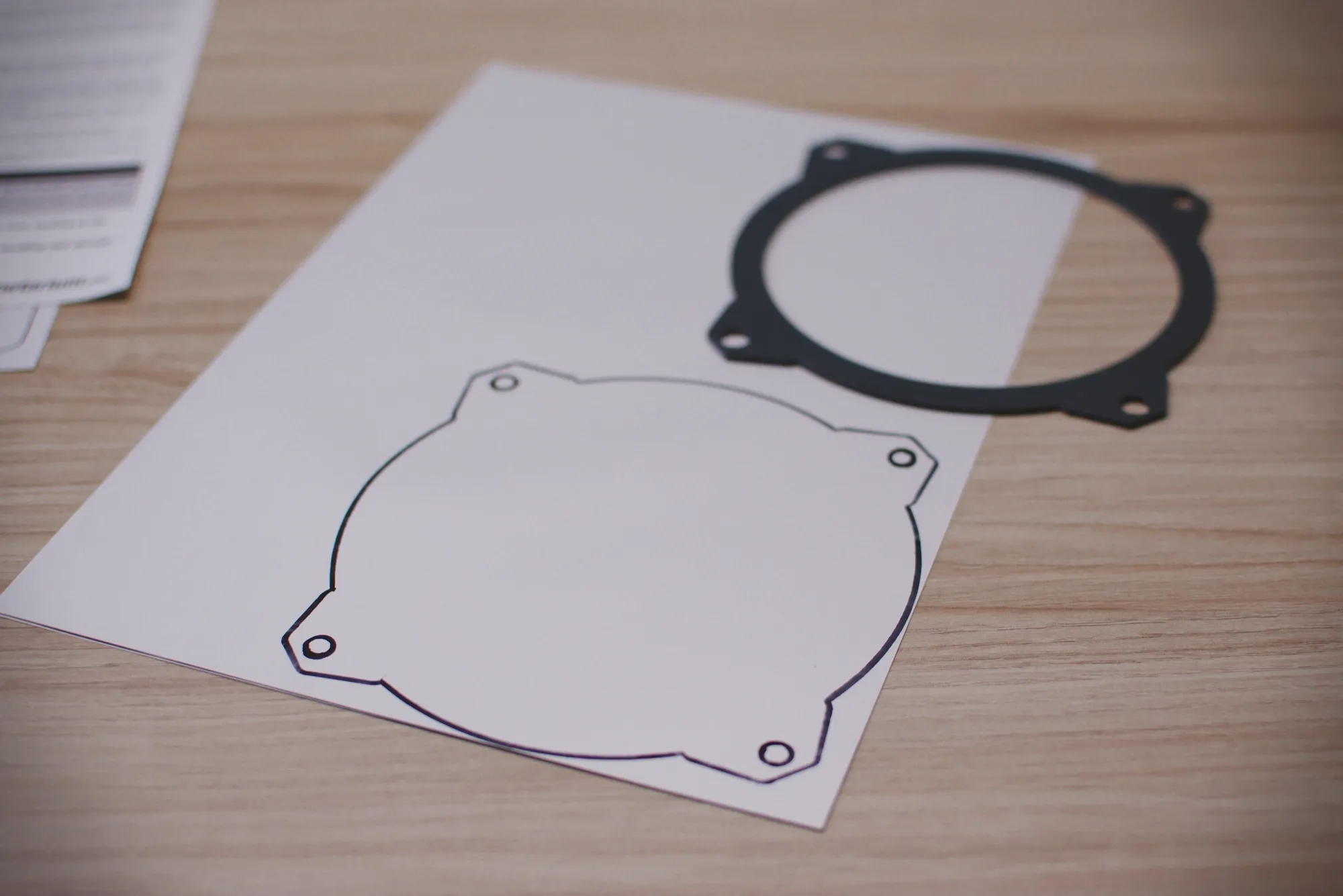
The template and the traced outline.
With the outline marked, you cut it, punch it with the hole punch (6 mm holes) and mount it inside the cell, between its two halves. The wrinkles you can see are normal — the film sits loose, which is exactly what we were after.
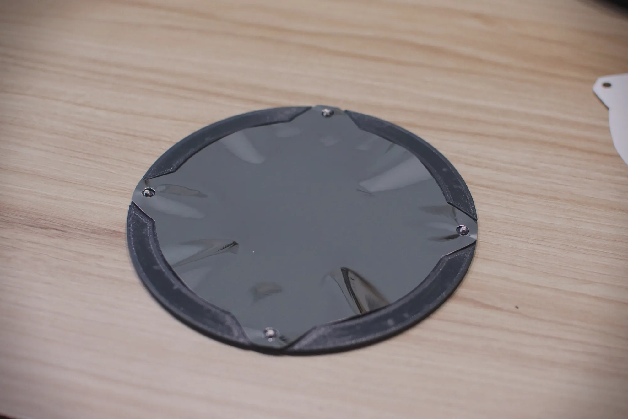
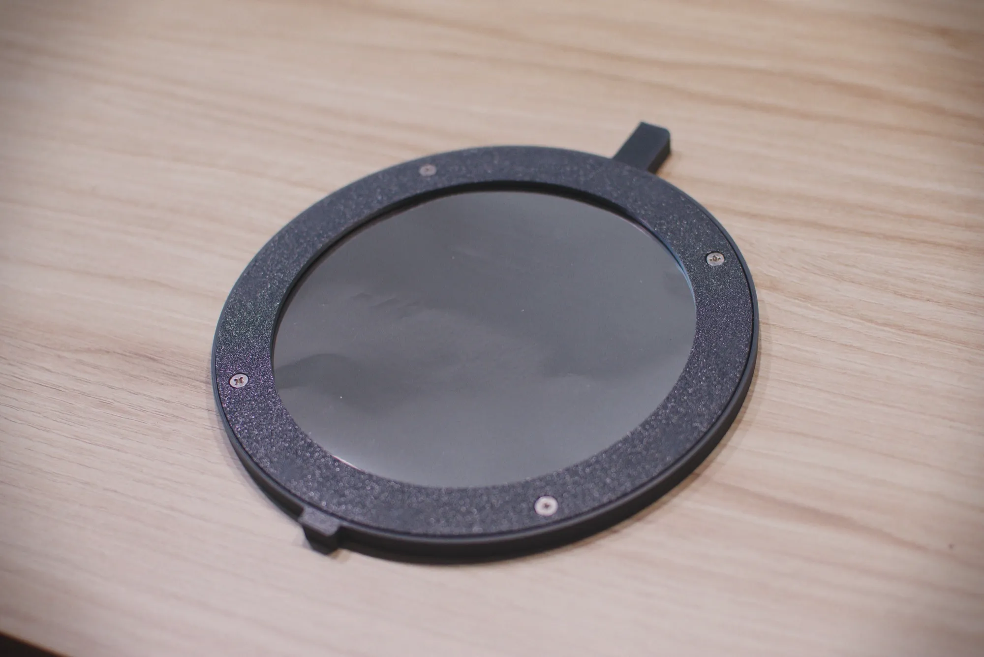
The cell assembled. The screws pass through the punched holes and hold the film without pulling on it.
The two caps
We ended up adding two caps to protect the film during storage and transport.
The front one is magnetic too — it reuses the magnets already in the cell — because it is meant to go on with the telescope already set up, capping the light and protecting the sensor. On the Sigma fp that sensor is fully exposed — the camera has no mechanical shutter at all.
Here, since those magnets already sat about 3 mm below the surface of the cell, we decided not to bury them with a print pause the way we did in the base, but to glue them into their pockets once the part is printed, flush with the contact face. That way we keep the gap between magnets as small as possible, and the cap holds fine.
The rear one closes the assembly from behind and has exactly the same diameter as the Mak 127. With both on, the parts stack and travel as a single block instead of rattling around loose in the bag.
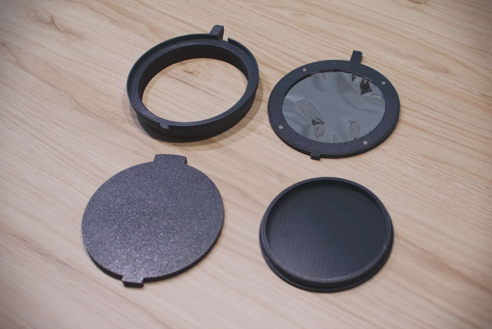
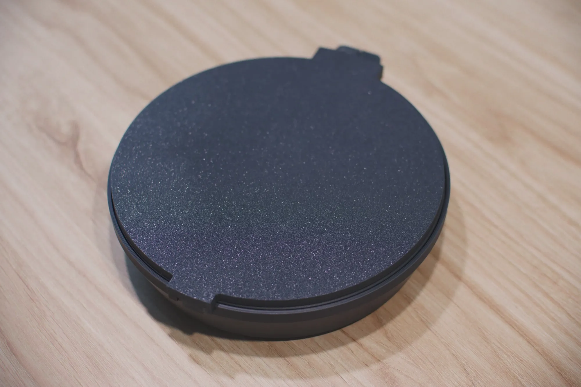
The four printed parts and, next to them, everything closed up to go in the bag.
The STL files are up on Printables in case anyone has the same scope. There are six of them rather than four, because the cell is two halves and the cutting template goes separately.
The test
With the filter finished all that was left was to mount it and try taking it off and putting it back — not pointed at the Sun, obviously — and it worked fine. The one thing to watch is not dropping it, since the magnets are strong and the film is very thin and would crease.
Taking the filter off and putting it back.
And with everything mounted — and after checking the film for pinholes and tears — it was time to point the telescope at the Sun and run some exposure tests:
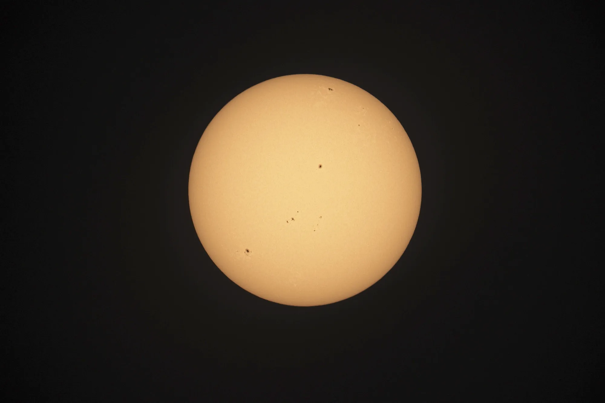
Shot through the Baader filter — 1500 mm f/12, 1/1000 s, ISO 640.
The disc comes out clean, with the sunspots resolved. The orange tone was added in post — through Baader film the Sun is very nearly white.
What actually matters is still ahead: planning the totality sequence properly, with the intervalometer doing its part.
References
- The STL files on Printables — the six parts, with printing notes
- Baader AstroSolar Safety Film OD 5.0 — the film
- Vibe coding 3D design with OpenSCAD and Claude Code — the setup the parts were designed with
- An intervalometer with the Raspberry Pi — the other half of the eclipse chain